
You have no items in your shopping cart.
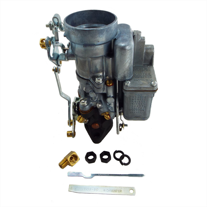
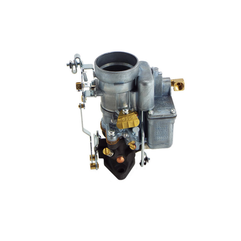
CARBURATOR CARTER WO JEEP MB/GPW NEW
Artikel unieke code: WO647843C
MPN: 1
GTIN (EAN,ISBN): 1
Fits Model : EARLY MB, MB, M201, CJ2A, CJ3A
Weight: : 2,1000 Kg
x2 3/8” UNF Nuts for fitting to engine block (225831)
x2 3/8” Washer for fitting to engine block
x1 90° Fuel Union (137422)
x1 Carter Float Level Adjustment Tool (T109-80)
x1 Cater Metering Rod Adjustment Tool (T109-26)
x1 Throttle Cable Trunnion and Screw (GPW-11495 WO-A8834)
x1 Carter Data Sheet
x2 3/8” Washer for fitting to engine block
x1 90° Fuel Union (137422)
x1 Carter Float Level Adjustment Tool (T109-80)
x1 Cater Metering Rod Adjustment Tool (T109-26)
x1 Throttle Cable Trunnion and Screw (GPW-11495 WO-A8834)
x1 Carter Data Sheet
Verkoopprijs: 339,77 €
Basisprijs280,80 €
Totaal BTW:58,97 €
X
CARTER CARBURETOR SERVICING AND ADJUSTMENT - MB
Note: Universal and will work for all Carter Carburetors
 Float Circuit:
If the float is loaded with fuel or if the holes for the pins are worn, the carburetor will flood. Poor action of the float needle will occur if the lip of the float bracket is worn. In this event, it should be smoothed with emery cloth. The needle and seat may leak because of wear, damage or sticking and will cause the carburetor to flood. Needles and seats are available only in matched sets. Never replace the needle without replacing the seat.
To determine the float level, Fig. 119, first turn the bowl cover gasket around and with the cover in position as shown, the float by its own weight should rest at 3/8" [9,525 mm.] (as indicated by the gauge). To change the float level press down with a screw driver on the brass lip of the float, holding up on the float while assembled to the cover of the carburetor. Bending the lip in this way allows it to retain its curvature which is necessary for the correct operation of the float valve. Be sure the spring and pin in the valve are in position and that the spring has not been stretched.

Low-Speed Circuit:
In the low speed circuit, Fig. 115, it will be found that the fuel does not come through the main metering jet, but through the idle well jet, and the low speed jet the openings of which are carefully calibrated. If they are damaged they should be replaced. The jets should always be tightly seated. The by-pass and air bleed holes must be clear. Carbon deposits which may form in the throat of the carburetor might restrict the air bleed holes to the extent that insufficient air will be supplied to mix the fuel before it reaches the idle port. This condition will usually be indicated if it is necessary to screw the idle mixture adjusting screw, in closer than the minimum limit of 1/2 turn. If the condition is bad, a rolling idle may continue even after the idle mixture adjusting screw is screwed entirely in against the seat. The air bleed holes may be cleaned with a soft copper wire. The idle port must be kept clean and unrestricted. If it is damaged the engine will not perform properly at low speeds and a new body flange will be required.
A letter "C" enclosed by a circle is stamped on the face of the throttle valve. When the valve is installed in the carburetor, this side should be toward the idle port, and facing the intake manifold as viewed from the bottom. To properly center the valve in the throat of the carburetor, the screws should be started in the shaft, and then with the valve tightly closed (throttle lever adjusting screw backed out) it should be tapped lightly. This will centralize the valve in the carburetor throat. Pressure should then be maintained with the fingers until the screws are tightened. If the carburetor throat is restricted with carbon deposit it will be necessary to open the throttle wider than the correct opening to obtain the proper engine idle speed. Opening the throttle more than this amount in order to obtain the proper idle will then uncover more of the slotted idle port than was intended. This will result in leaving an insufficient amount of the idle port as a reserve to cover the period between idle and 20 miles [32 km.] per hour, where the high speed system begins to cut in. A flat spot on acceleration will result. Clean by scraping with emery cloth.

High-Speed Circuit:
It is rarely necessary to remove the main nozzle Fig. 116. It can usually be cleaned by removing the plug and blowing it out with compressed air. If it is damaged and requires replacing, make sure, upon installation that only one gasket is between the nozzle and the seat. If the carburetor has been in service for a long time or has been tampered with, it may be found that the metering rod is improperly adjusted or worn. A worn metering rod will have the effect of a rich mixture above 20 miles per hour (32,2 k.p.h.). If the metering rod is worn, the metering rod jet will also be worn and both should be replaced. Before adjusting the metering rod adjust the accelerating pump stroke, for the pump stroke adjustment will change the metering rod setting.
To adjust the metering rod, back out throttle lever adjusting screw "C", Fig. 120, and close the throttle tight. Using gauge T-109-26, Fig. 120, (supplied by Carter Carburetor Co.) loosen nut "B" and move pin until it seats in the notch of the gauge. Tighten the nut securely. Remove the gauge and install metering rod with disc, and connect the spring through hole in the metering rod.


Accelerating Pump Circuit:
Accelerating Pump Circuit If the pump plunger is worn, sticks or if the spring under the leather has lost its tension, replace the plunger assembly, Fig. 113. If the pump intake check valve, Fig. 117, leaks part of the pump discharge will be forced back through the valve into the float bowl, preventing a sufficient amount of fuel to be discharged from the jet. If the valve can not be cleaned with compressed air, it must be replaced. If the pump discharge check valve leaks, air will be drawn into the pump cylinder on the up stroke of the plunger. This gives an insufficient discharge of fuel into the throat of the carburetor on acceleration causing a flat spot. If the valve can not be cleaned with compressed air, to prevent leakage, it must be replaced. If the accelerating pump arm spring is weak or damaged, it will cause poor acceleration. If the hole in the accelerating pump jet is too large, the accelerating charge will be allowed to pass too fast and will make the mixture too rich. An enlarged jet must be replaced. A loose jet gives the same effect. A clogged jet will cause a flat spot on acceleration. To adjust the pump stroke, pump gauge T-109-117C should be used.
First back out the throttle adjusting screw "C", Fig. 120, to fully close the throttle. To measure the stroke, place the gauge on top of the bowl cover, Fig. 121, open the throttle wide and measure to the top of the pump plunger rod. Close the throttle tight and measure again. The difference, which is the pump stroke, should be 17/64" [6,747 mm.] To adjust the stroke bend the throttle connector rod at "A".


IMPORTANT: Always set the pump stroke before setting the metering rod. If set afterwards the metering rod will be thrown out of adjustment. If the throttle connector rod and throttle shaft arm assembly are worn, it will allow the throttle valve to be opened by the accelerator pedal before the pump begins to discharge fuel, resulting in a flat spot. Replace all worn parts because the operation of the metering rod is also affected.
")
")
")
")